
Source Description:
Dimensions for the I-Plant seed 1,2,3,4 are taken from the study by Rivard. The I-Plant seed has a Ti capsule with an outside diameter of 0.836 mm and end welds which are 0.330 mm thick spherical sections. The end welds are modelled using a 0.225 mm thick section of a 0.500 mm radius Ti sphere attached to a 0.105 mm thick Ti cylinder with a radius of 0.418 mm. The wall thickness of the Ti capsule is 0.0558 mm. Inside the source there is a Ag marker assumed to have a total length of 3.60 mm and a radius of 0.200 mm. The conical ends of the marker have a half-angle of approximately 18 o . The active element of the source is a quartz tube surrounding the marker that is 3.76 mm in length and has inside and outside diameters of 0.432 mm and 0.635 mm, respectively. The quartz tube is covered in a 16.0 μm thick active layer of Si containing 124 Xe which is in turn covered by a 5.00 μm thick layer of Si0 2 . The active layer is assumed to have a density of 2.58 g/cm 3 and is composed of 97.6% Si, 2.38% Xe, 1.60x10 -3 % I and 6.00x10 -4 % Te. The overall length is 4.60 mm and the active length is 3.76 mm. The cylindrical source element is free to move approximately 0.090 mm along the seed axis and 0.056 mm radially from the center of the seed.Dose Rate Constant - Λ :
Dose rate constants, Λ , are calculated by dividing the dose to water per history in a (0.1 mm) 3 voxel centered on the reference position, (1 cm,Π/2), in the 30x30x30 cm 3 water phantom, by the air kerma strength per history (scored in vacuo ). As described in ref. 5 , dose rate constants are provided for air kerma strenth calculated using voxels of 2.7x2.7x0.05 cm 3 (WAFAC) and 0.1x0.1x0.05 cm 3 (point) located 10 cm from the source. The larger voxel size averages the air kerma per history over a region covering roughly the same solid angle subtended by the primary collimator of the WAFAC 6,7 at NIST used for calibrating low-energy brachytherapy sources and is likely the most clinically relevant value. The small voxel serves to estimate the air kerma per history at a point on the transverse axis.
| Author | Method | Λ (cGy h-1 U-1) | Abs. Uncertainty |
| R. E. P. Taylor, D. W. O. Rogers 8 | WAFAC | 0.994 | 0.002 |
| R. E. P. Taylor, D. W. O. Rogers 8 | point | 0.998 | 0.003 |
| M. J. Rivard 1 | extrap. (MCNP) | 1.017 | 0.005 |
| R. E. Wallace 4 | TLD | 1.01 | 0.04 |
| D. Duggan, B. L. Johnson 3 | TLD | 1.01 | N/A |
| M. J. Rivard et al 9 | Consensus Value | 1.014 |
Radial dose function - g(r):
The radial dose function, g(r), is calculated using both line and point source geometry functions and tabulated at 36 different radial distances ranging from 0.05 cm to 10 cm. Fit parameters for a modified polynomial expression are also provided 10 .
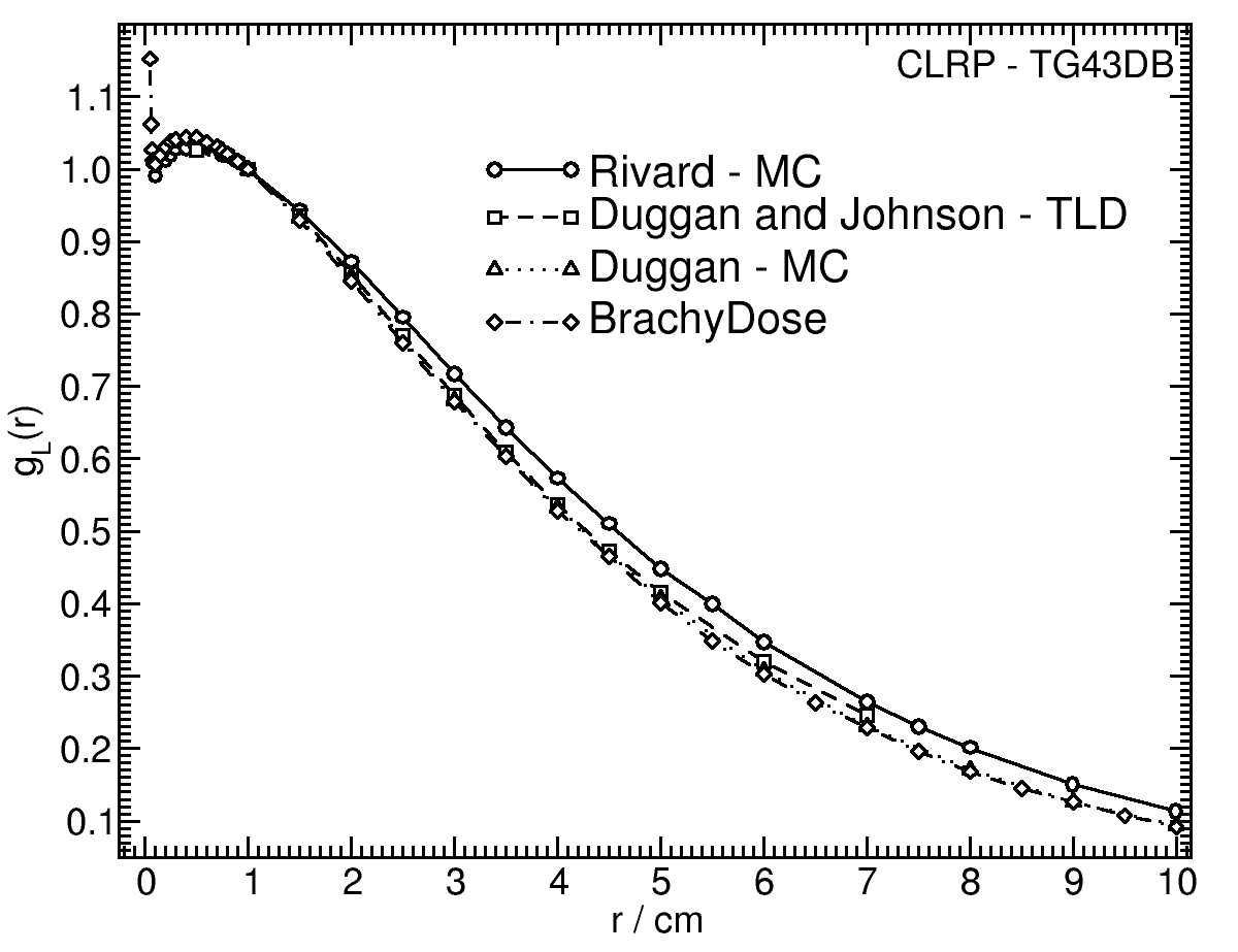
| Fitting coefficients for g L (r) = (a 0 r -2 + a 1 r -1 +a 2 + a 3 r +a 4 r 2 + a 5 r 3 ) e -a 6 r | ||||||||
| Fit range | Coefficients | |||||||
| r min (cm) | r max (cm) | a 0 / cm 2 | a 1 / cm | a 2 | a 3 / cm -1 | a 4 / cm -2 | a 5 / cm -3 | a 6 / cm -1 |
| 0.05 | 10.00 | 1.1109E-03 | -2.0318E-02 | 1.1009E+00 | 4.5785E-01 | -7.7001E-03 | 1.7638E-03 | 4.2760E-01 |
Anisotropy function - F(r,θ):
Anisotropy functions are calculated using the line source approximation and tabulated at radii of 0.1, 0.15, 0.25, 0.5, 0.75, 1, 2, 3, 4, 5, 7.5 and 10 cm and 32 unique polar angles with a minimum resolution of 5 o . The anisotropy factor, φ an (r), was calculated by integrating the solid angle weighted dose rate over 0 o ≤ ϑ ≤ 90 o .
F(00.25,θ) 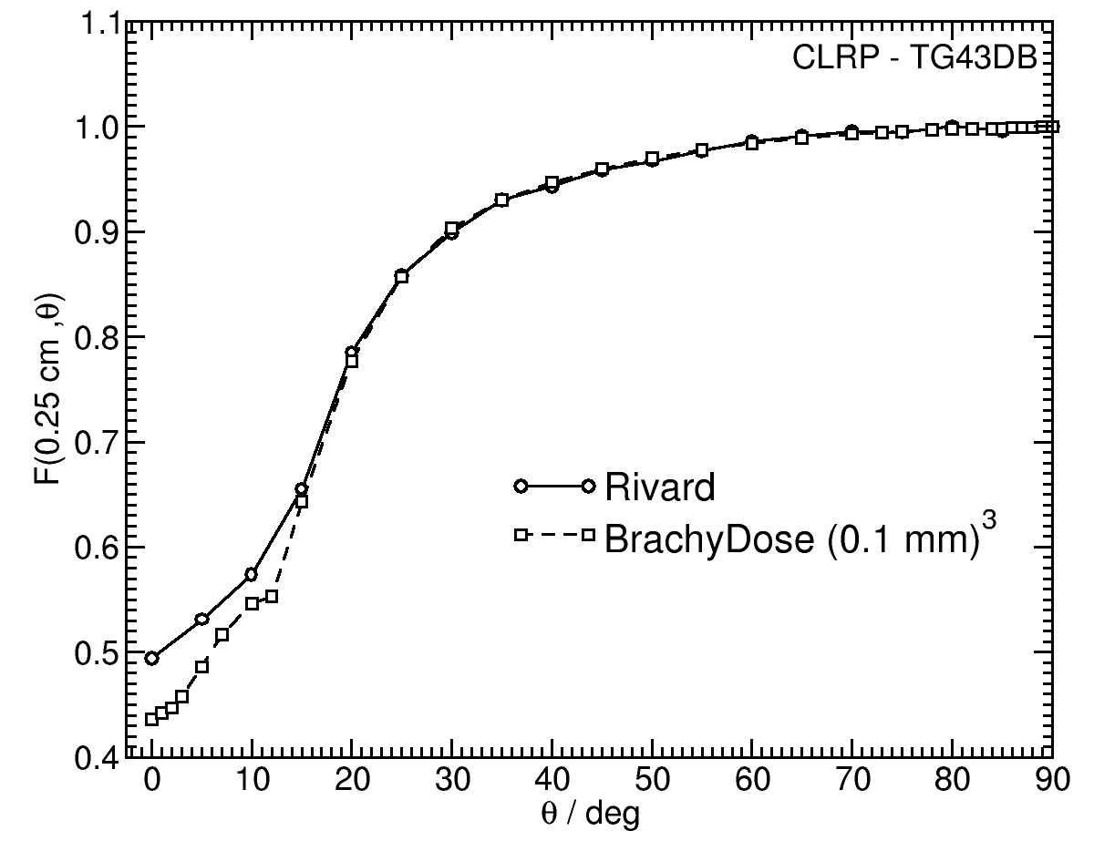 |
F(00.50,θ) 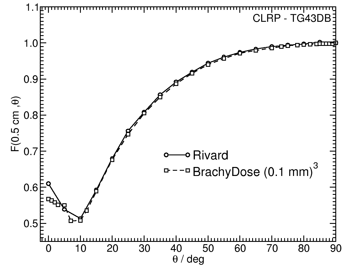 |
F(01.00,θ) 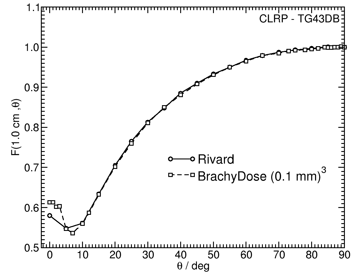 |
F(05.00,θ) 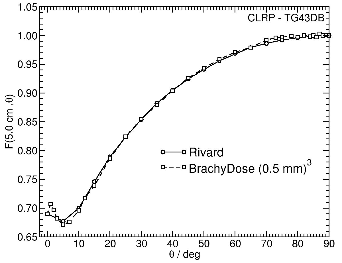 |
References:
1. M. J. Rivard, Comprehensive Monte Carlo calculations of AAPM Task Group Report No. 43 dosimetry parameters for the Model 3500 I-Plant 125 I brachytherapy source, Appl. Radiat. Isotopes, 57 , 381 -- 389, 2002
2. D. Duggan, B. L. Johnson, Improved radial dose function estimation using current version MCNP Monte Carlo simulation: Model 6711 and ISC3500 125I brachytherapy sources, Appl. Radiat. Isotopes, 61 , 1443--1450, 2004
3. D. Duggan, B. L. Johnson, Dosimetry of the I-Plant Model 3500 iodine-125 brachytherapy source, Med. Phys., 28 , 661--670, 2001
4. R. E. Wallace, Model 3500 125 I brachytherapy source dosimetric characterization, Appl. Radiat. Isotopes, 56 , 581--587, 2001
5. R. E. P. Taylor et al , Benchmarking BrachyDose: voxel-based EGSnrc Monte Carlo calculations of TG--43 dosimetry parameters, Med. Phys., 34 , 445 -- 457, 2007
6. R. Loevinger, Wide-angle free-air chamber for calibration of low--energy brachytherapy sources, Med. Phys., 20 , 907, 1993
7. S. M Seltzer et al , New National Air-Kerma-Strength Standards for 125 I and 103 Pd Brachytherapy Seeds, J. Res. Natl. Inst. Stand. Technol., 108 , 337 -- 358, 2003
8. R. E. P. Taylor, D. W. O. Rogers, An EGSnrc Monte Carlo-calculated database of TG-43 parameters, Med. Phys., 35 , 4228--4241, 2008
9. M. J. Rivard et al , Supplement to the 2004 update of the AAPM Task Group No. 43 Report, Med. Phys., 34 , 2187 -- 2205, 2007
10. R. E. P. Taylor, D. W. O. Rogers, More accurate fitting of 125 I and 103 Pd radial dose functions, Med. Phys., 35 , 4242--4250, 2008
Carleton Laboratory for Radiotherapy Physics
December 17 2007.